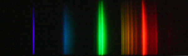
Spectrum of a compact fluorescent bulb, taken
with an Aruna-1 spectrometer and a DSLR camera..


Last revised on Sunday, 27-Jul-2025 17:06:42 EDT
©1998--2026 Creative Consulting for Research and Education
You will need the following tools and materials
to assemble the spectrometer:
Additional tools that may be needed: thin round metal file
a) Before fastening components together with screws, check the alignment of the through-holes on one component, with the pilot holes for the screws on the other component. Since the pilot holes are drilled into wooden components, there is a good bit of tolerance in the alignment. However, if the overlap of the holes is off by more than about 20%, you may consider elongating the through holes, in the appropriate direction, using a round metal file.
b) When fastening components which should be at right angles in the horizontal plane, in particular, when mounting the mask plate to the base plate, hold the components firmly together in the proper orientation when fastening, or they may rotate as you screw them together.
c) Since most components are made from wood, they are not designed to be repeatedly disassembled and reassembled — the screws won't be gripped as tightly after they are removed once. However, even in the case where the screws don't tighten down completely, as long as the two components are rigidly mated without any wobble, there is no need for concern. In the event the two components are not rigidly mated, it should be possible to apply some wood filler (Elmer's wood filler, for example) to the screw threads, to regain a firm hold between the two components.
Place the two Entrance Slit knife blades on the Slit Plate
as shown in the picture below.

Position the knife blades to cover the vertical length of the aperture in
the slit plate, so that they form a narrow vertical slit in the horizontal
center of the slit plate aperture. You will want to achieve a slit width of
approximately the thickness of a hair, and it may take a couple of trials
to obtain a usefully narrow slit.
Remove one of the blades temporarily, leaving the other one in position. Cut several small strips of black electrical tape, 3/4" by about 3/8–1/2" wide, and have them ready. Placing your finger on the blade in position and pressing down to hold it in position, affix one of the tape strips to hold the blade, on its left edge, to the plate. Then, use another strip to hold the blade on its right edge. Do not obscure the slit area with the tape.
Place the other blade back into position, and hold it position with two tape
strips also. The assembly should look as shown below.

Hold up the slit and look at a light source through the slit to check its width
and overall rotation from vertical. If the slit appears too wide, or is not
vertical with respect to the edges of the plate, remove the tape strips from one
or both blades, re-position the blade(s), and re-affix with the tape strips.
Although it may seem that you should make the slit as narrow as possible, avoid the temptation to do so. A very narrow slit has the disadvantages that it will admit less light, making the observed spectra dimmer, and is susceptible to being obscured by dust, creating horizontal dark lines in the spectrum. The slit should be less than about half of a millimeter in width, however.
Once the entrance slit is formed to the anticipated width and vertical orientation, use additional tape strips, at the top and bottom of the blades, to hold them securely to the slit plate.
Next, attach the assembled Slit Plate to the front of the Base Plate, using three #4-1/2" screws. Hold the slit plate firmly in position while tightening the screws.
Using two #6-3/4" screws, attach the Grating Holder to the Base Plate. Use the set of two through holes farthest to the back of the base plate (holes farthest from the slit plate). The correct orientation of the grating holder will result in the warning sticker facing the back of the spectrometer.
Using two #6-3/4" screws, attach the Mask Plate to the Base Plate. Use the set of two through holes in the base plate which are three inches in front of the grating holder mounting holes. The black side of the mask plate faces the grating holder. Hold the mask plate firmly when tightening the screws from below the base plate, so that it does not rotate with respect to the base plate.
Using four #4-5/8" screws with #6 flat washers, attach the Top Plate to the top of the Mask Plate. The black-painted side of the top plate should face down towards the base plate.
Using one #6-3/4" screw, from the top of the base plate, attach the hand grip, using the end of the hand grip with the pilot hole. Tightening this screw will require a bit more torque, since the pilot hole is made narrower to ensure a very tight mating with the base plate. Use one of the center-drilled holes on the base plate (3a–3c on the base plate drawings) for attaching the hand grip: 3a for the 6", 3b for the 8", and 3c for the 10" base plate.
Cut, fold, and tape the black poster-board to the open part of the spectrometer between the slit plate and mask plate, to shield the grating from light paths other than through the entrance slit. See the Aruna-1 Drawings Folder for the light shield dimensions, and the fold lines, for the different base plate lengths. Use strips of electrical tape to hold the light shield onto the spectrometer. The front of the shield should overhang the slit plate by about 1". Use the tape to ensure that no light passes into the spectrometer from around the edges of the slit plate.
Congratulations! You are now ready to use your Aruna-1 spectrometer!
The light from a compact fluorescent (CF) bulb will allow you to check the
performance of your newly assembled spectrometer with your vision. Aim
the spectrometer at a CF light and compare your observed spectrum with the
spectrum shown below. In particular, check whether or not you are able to
resolve the two closely-spaced yellow lines of mercury shown in the picture.
These spectral lines have air wavelengths of 577.0 nm and 579.1 nm.
If you are easily able to resolve these two lines, then your spectrometer has a
spectral resolution of at least 1 nm.