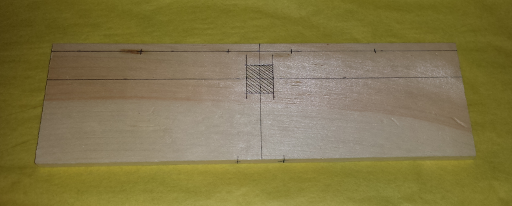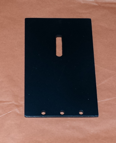
Place the marked base plate blank on a scrap wooden piece with a flat surface, such as a piece of 2"x6". Start with a 5/64 drill bit, and drill pilot holes for all of the marked holes. For the base plate, every hole on the top surface is a through hole, and the holes on the front end, for mounting the slit plate, should be drilled to at least 1/2" depth. Follow the drill table specifications for the hole diameter, given in terms of the drill bit size, and hole depth. The hole number in the drill table corresponds to the hole number on the corresponding drawing. From the 5/64 size, gradually increase the drill bit size to enlarge the hole in steps, until you have drilled the specified bit size.
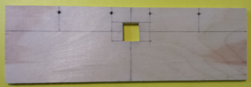
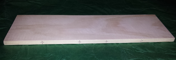
After all holes have been drilled to the proper size and depth on the base plate, use very fine 220 grit sand paper to smooth all surfaces and remove any burrs from the base plate. Also use a thin round metal file to smooth any roughness inside and around the holes. Wipe the base plate clean with a lint-free cloth or paper. The base plate is ready for painting. We recommend fabricating all parts before painting, since several parts may be painted at the same time.
Grating Holder
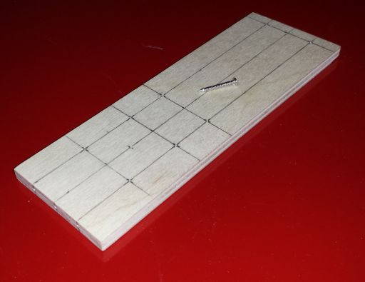
Refer to the grating holder drawings. Using a small hacksaw, cut two pieces, 1 1/2" long from the same 2" wide wood stock from which the base plate was cut. These are pieces A and B of the grating holder. Sand the top and bottom edges (2" sides) of these two pieces, as needed, to obtain flat square edges. Use the carpenter's square to judge the flatness and corner angle with respect to the side edges. On piece A, choose the bottom edge as the one which has the best flatness and is square with respect to the sides, since this side will mate with the base plate. Mark the two mating holes on the bottom of piece A using a ruler and pencil, punch guide holes, and drill the holes to specified bit size and depth indicated on the drill table. Once again, start with a 5/64 bit to make a pilot hole. Small centering errors on the pilot holes may be corrected as the holes are enlarged to their final size.
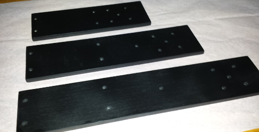
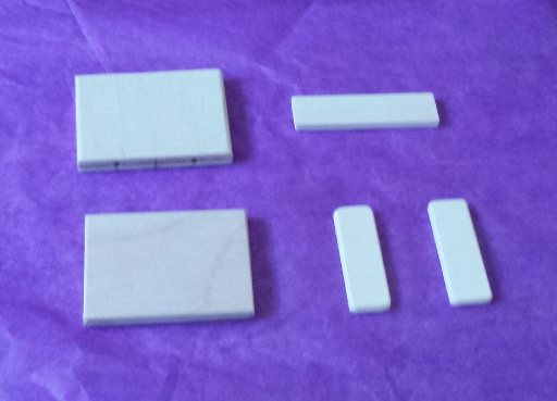
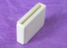
The remaining pieces of the grating holder, C--E, are cut from the 1/8" x 1/2" x 24" wood strip: piece C is 2" long, and D--E are 1 1/2" long. Sand the edges of these pieces to remove any irregularities from the cuts. A picture of all five pieces, A--E are shown above. The pieces have been lightly sanded, and the outward facing edges have also been rounded, using sandpaper, for a nicer look and feel. The pieces are ready to be glued together as shown in the grating holder drawings, page 2.
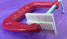
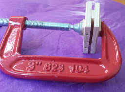
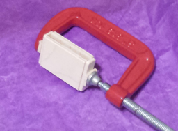
On piece A, draw a line on the inside edge, parallel to the bottom edge, and 1" above the bottom. This line will mark the edge of piece C, which is glued to A, as shown above. Ordinary glue, like Elmer's school glue works well, but if you want a stronger bond between the pieces, you may use a carpenter's wood glue. A 3" C-clamp, with flat wooden pads attached to the ends of the clamp using double-sided tape, is useful for holding the pieces together with a little pressure while the glue is setting, making for a stronger bond. After about one hour, remove the clamp and glue piece B to the other side of C, being sure to align the top and side edges of A and B. Clamp as shown above. Finally, the side pieces, D and E are glued and clamped to the grating holder. Center the side pieces on the edges, and flush with the top of the grating holer. Allow the glue to set for 24 hours. The completed grating holder is then ready for painting, as shown below.
Slit Plate
Mask Plate